Project PROMISE is more than a research initiative—it’s a platform for collaboration, innovation, and knowledge transfer. By addressing both technological and societal challenges, PROMISE aims to make solar energy a cornerstone of Malta’s energy strategy.
The Foundation for Innovation and Research – Malta and Anhalt University posted online 6 video lectures produced as part of the PROMISE project.
You will find below a description of each video and a link to view it.
Access to the videos requires registration. Once you complete the registration, you will receive a password, which is needed to view the videos.
Abbreviations :
PV: Photovoltaic
BOS: Balance of Systems
MPPT: Maximum Power Point Tracker
SOC: State of Charge
DOD: Depth of Discharge
HSa – introduction
Overview
In this opening video, Prof. Dr. Carlos Meza sets the stage for the PROMISE teaching series and explains how it connects to the wider goals of the project. He introduces the collaborative network of universities, research institutes, and industry partners working together in PROMISE, and shows how education is at the heart of this effort.
The lecture highlights the Master’s program in Photovoltaics Engineering Science at Hochschule Anhalt, particularly the Storage Systems module, where students learn how energy storage enhances PV performance and flexibility. Prof. Meza emphasizes that the videos are meant to share not just technical knowledge, but also the spirit of innovation and collaboration that drives PROMISE.
Key Topics Covered
- The PROMISE consortium and its role in research and education
- Why training materials on PV and storage are crucial for the future energy system
- The structure of the Storage Systems module, including stand-alone and grid-connected design
- How simulation and modeling tools help students understand PV system behavior
Learning Outcomes
After watching this video, viewers will:
- Gain an understanding of the PROMISE Project and its educational mission
- Learn how storage systems are integrated into PV teaching modules and why they are essential for future energy systems.
- Recognize the scope of the training material shared through PROMISE, including the focus on stand-alone system sizing
- Discover opportunities for deeper engagement through the Master’s program at Hochschule Anhalt.
HSA – Part1: Context
Overview
This video introduces the fundamental context for designing stand-alone PV systems with integrated storage. Prof. Dr. Carlos Meza explains why storage is necessary to balance generation and consumption, given the natural variation of both loads and solar input. The lecture clarifies how balance-of-system (BOS) components bridge the gap between the PV generator and loads, ensuring stability and reliability.
The focus is on providing students with a framework for understanding stand-alone PV systems. By narrowing attention to the most critical BOS components—batteries, charge controllers, and inverters—the lecture sets the stage for more detailed design discussions in subsequent parts of the series. Other parts, such as wiring and protections, are noted but set aside for later.
Key Topics Covered
- Importance of storage for matching fluctuating generation and demand
- General objective of a stand-alone PV system: balance energy flow and maximize battery lifetime
- Main system elements and the focus on three BOS components (inverter, battery, charge controller)
- First discussion of what “design” means: deciding how to connect and select components
Learning Outcomes
After watching this video, viewers will:
- Understand why storage is fundamental for stand-alone PV systems
- Be able to name the most important system components and their functions
- See how batteries, inverters, and charge controllers form the basis of design decisions
- Begin to think of design not only as selecting devices but also as connecting them in a way that reliably meets load demand
HSa – PART2: DESIGN
Overview
This lecture marks the start of the step-by-step design process for stand-alone PV systems. Prof. Dr. Carlos Meza introduces a structured design flow, emphasizing that while steps are suggested in order, real-world design is iterative. Designers often revisit earlier steps when faced with constraints such as limited space, high peak loads, or component availability.
The video highlights why the process begins with load characterization. Unlike grid-connected systems, where PV array capacity often drives design, stand-alone systems must prioritize demand because their core objective is reliable load supply. Students are shown how to quantify loads, describe their dynamics, and understand their timing to create a foundation for sizing inverters, batteries, and PV arrays.
Key Topics Covered
Suggested seven-step framework for stand-alone PV design
Why the process begins with load characterization instead of PV capacity
Building a load table with nominal power, peak power, hours of use, and timing
How inductive loads create inrush currents that must be accounted for
Defining the system voltage (12 V, 24 V, 48 V) as an early step in guiding the rest of the design
Learning Outcomes
After watching this video, viewers will:
- Recognize why load analysis is the foundation of stand-alone PV system design
- Learn how to describe and quantify loads accurately
- Understand the role of peak power and why it affects inverter choice
- Apply practical guidelines for choosing system voltage based on load size and available components
- Appreciate the iterative nature of system design and the need to revisit steps as constraints arise
HSA – Part3: DESIGN 2
Overview
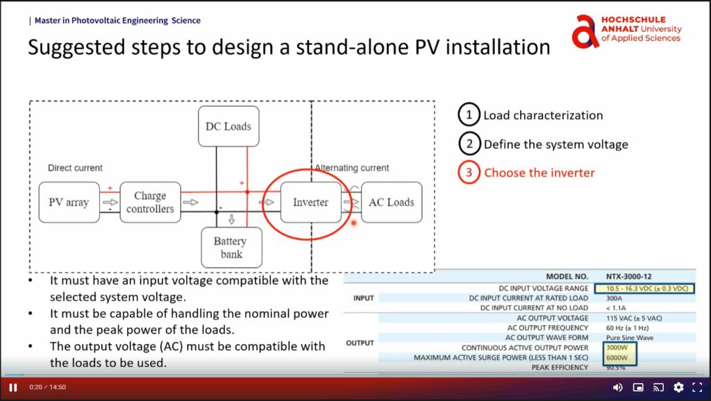
This lecture focuses on the stand-alone inverter, the device that converts DC power into usable AC power for loads. Prof. Meza makes clear that sizing and selecting this component is very different from grid-connected systems, since here the inverter must be matched to the loads, not the PV array.
Students are guided through inverter datasheets, where values such as nominal power, surge power, and input voltage ranges are explained in detail. Prof. Meza also compares stand-alone and grid-connected inverters, showing how the same circuit topology can serve different purposes when combined with different algorithms and control goals. Finally, he explains waveform options, from square wave to pure sine wave, and their implications for different kinds of appliances.
Key Topics Covered
Stand-alone inverter role: provide AC supply to loads when PV is the only source
Sizing based on load requirements (nominal and surge power)
Input/output parameters and their compatibility with batteries and loads
Comparison of grid-connected and stand-alone inverters
Waveform types: square wave, modified square wave, and pure sine wave
Learning Outcomes
After watching this video, viewers will:
- Understand why stand-alone inverters are sized according to load demand
- Learn to read and interpret inverter datasheets
- Distinguish between stand-alone and grid-connected inverters in design and function
- Recognize how waveform choice affects load compatibility and system complexity
- Build a foundation for linking inverters with batteries and charge controllers in a complete design
HSa – PART4: DESIGN
Overview
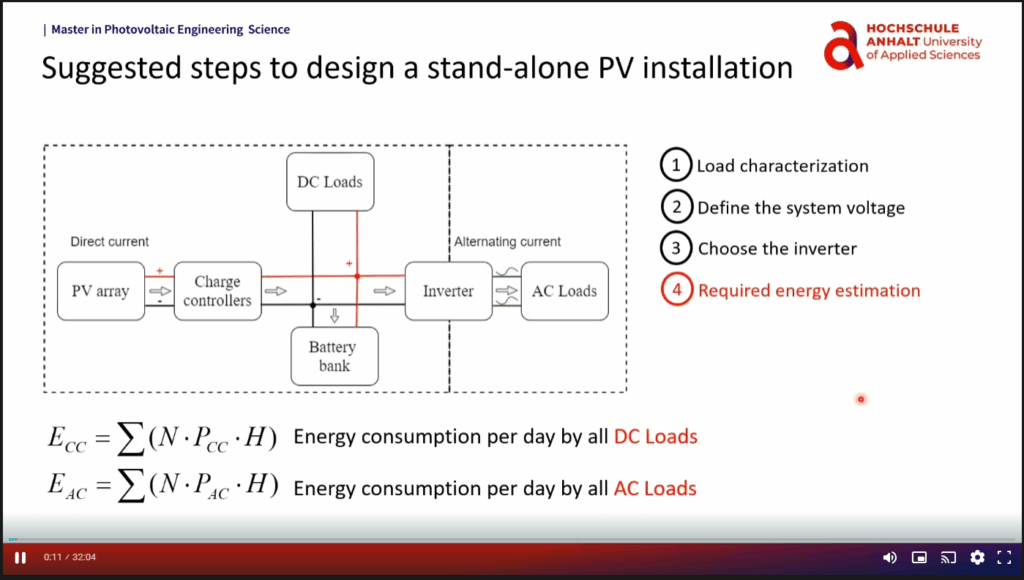
This video takes the next step in the design process: estimating required energy and designing the battery bank. Prof. Meza demonstrates how to calculate the energy needed each day, apply conversion losses, and then size the battery storage accordingly. Batteries are highlighted as one of the most critical and expensive parts of the system, so proper sizing is essential.
The lecture also introduces practical concepts such as depth of discharge (DOD), cycle life, and days of autonomy. Through worked examples, Prof. Meza shows how datasheet values can be used to determine how many batteries are needed, how they should be connected, and how operating choices affect lifetime.
Key Topics Covered
Separating DC and AC load energy and applying inverter efficiency factors
Accounting for system losses conservatively in design
Battery capacity ratings in Wh and Ah, discharge rates (C-rates), and temperature effects
Using datasheet specifications for max charge/discharge current to determine minimum parallel strings
How DOD affects cycle life and the trade-offs involved
SOC/DOD dynamics over a daily cycle
Days of autonomy as a safeguard against extended low-sun conditions
Learning Outcomes
After watching this video, viewers will:
- Calculate daily energy requirements, including losses and efficiencies
- Translate datasheet parameters into real design choices
- Understand how to configure batteries in series/parallel to meet current and voltage requirements
- Apply DOD and autonomy considerations to balance reliability with cost
- Appreciate how battery performance depends on environmental and operating conditions
HSA – Part5: DESIGN
Overview
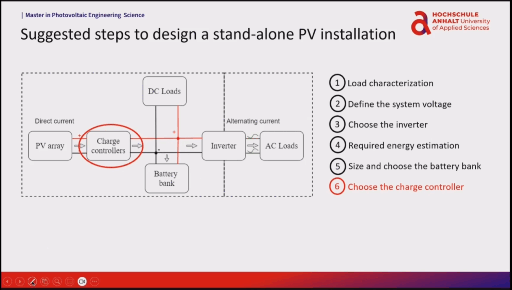
This session completes the stand-alone PV design workflow by (1) choosing the charge controller, (2) sizing the PV array, and (3) wrapping up with design checks and the reminder that the process is iterative. The charge controller is presented as the device that connects the PV array to the battery, ensuring that energy flows properly into the system while protecting the storage from damage. Prof. Meza explains how MPPT algorithms track changing conditions to keep the array at its maximum power point, while also regulating how batteries are charged through bulk, absorption, and float stages.
The lecture then moves to PV array sizing, where daily energy demand is translated into required array power using peak sun hours. Students see how module choice and grouping are tied to charge controller ratings, and why multiple controllers may be needed in larger systems. Seasonal variations are discussed, highlighting the trade-off between designing for winter reliability and avoiding unnecessary oversizing.
Key Topics Covered
Functions of the charge controller: MPPT, charging stages, and protective roles
Datasheet compatibility and sizing formulas for controller selection
PV array sizing using worst-case energy and PSH data
Determining module counts and grouping strategies
Seasonal adjustments in design for high-latitude or strongly variable conditions
Importance of protections and why system design must be iterative
Learning Outcomes
After watching this video, viewers will:
- Understand the dual role of charge controllers in maximizing PV output and protecting batteries
- Select appropriate charge controllers based on voltage and current ratings
- Translate energy demand and PSH into PV array size and module count
- Account for seasonal variation in load and irradiance when making design decisions
- Recognize the iterative nature of design and how each step feeds back into the others